

Patent Attorney and Founder
Patent drawings are a vital and often overlooked aspect of the patent application process. These detailed, precise diagrams provide a visual representation of an invention, helping to elucidate the unique features and functionality that set it apart. Not only do they bring clarity to your written description, but they also play a crucial role in shaping the examiner’s understanding and interpretation of your invention. Simply put, an effective patent drawing can make the difference between a granted patent and a rejected application, underlining the importance of giving these illustrations due attention and care.
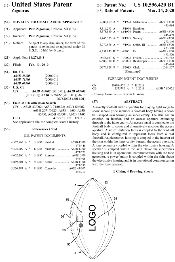
If I showed you the front cover sheet of a brand new patent (for example, US Patent 10,596,420 for a “Novelty Football Audio Apparatus” issued in March 2020)…
Where do you look first?
Don’t lie… your eyes went to the football image first, right?
…It’s human nature to do so, so don’t feel bad.
What Are Patent Drawings?
Patent drawings are graphic representations or diagrams that accompany a patent application to visually demonstrate the invention in question. They offer a visual guide that details the invention’s unique features, how it operates, and how it could be produced. Patent drawings can depict anything from simple mechanical devices to complex technological systems, architectural structures, or intricate chemical compounds. The primary purpose of these illustrations is to make the invention easier to understand, supplementing the often technical and complex written description.
The United States Patent and Trademark Office (USPTO) has outlined specific guidelines for these drawings. They must be clear, concise, and capable of reproduction when printed. All drawings must be in black and white, with exceptions made for color drawings if they are the only practicable medium to disclose the subject matter sought to be patented.
The drawings should be made with the assistance of a draftsman, if possible, and every feature of the invention specified in the claims must be depicted. Furthermore, reference numerals must be used to identify elements in the drawing, and these numbers should correspond with the elements described in the detailed description of the patent application.
Patent drawings for utility patent applications are the second major way that inventors (and their Patent Attorneys) are able to explain their invention (apart from words), and more particularly, what they are claiming they have invented.
Drawings are the only way in which inventors may disclose their inventions for design patent applications. So, they are really important for design patents.
In the front cover figure of the “Novelty Football Audio Apparatus” (I’m so excited for Football season, I just had to include this example) you can see there are numbers and markings that we will use throughout this article. Take a close look and make note of the different lines, markings, and shadings.
We will cover what all of these mean and more in this article. I hope you are at least (in part) a football fan, and if not, you can appreciate the use of this example of a simple three-dimensional product so you can follow along with me as we learn about patent drawings.
Section 1: Why Include Patent Drawings?
The entire goal of a patent application is to explain your invention as well as possible so that at least one version of your invention can be made/used by persons of skill in the art. To that end, if drawings would help achieve that goal, then they should be included.
It’s cliche, but “a picture is worth a thousand words” is so true – in that an inventor can save time/effort trying to describe something in words, when they can just show it in a drawing, and then discuss the drawing in words to support it.
There are some real bonuses to having drawings as well. One of the biggest advantages is the ability to grow a patent portfolio, and file child patents that claim the priority back to the first-filed parent application.
For example, a nonprovisional patent application (the parent) is filed and then it is found that while the parent is going through prosecution (patent pending) – a new improvement of the invention works better than the original one, and the inventor would like to try to file a patent application on the improvement. If the original specification (including the drawings) discussed this improvement (or basis for it), then the priority date can be claimed (either for a subsequent utility or design patent) for that child patent application (usually in the form of a divisional or continuation patent application).
If you didn’t totally follow that – the simpler version is: include drawings in ALL of your patent applications, because you will only improve your chances of being able to claim priority back to the original filing and build a portfolio (several patents) based on the one disclosure (words and drawings).
Hehe, not sure I was able to simplify it much there – but hope that helped.
There are some types of patent illustrations that will contain more important information than the written specification. This is definitely true for design patents but is also true for inventions for electric circuits and even some mechanical inventions, where shapes, surfaces, and textures are being claimed.
If a patent is ever litigated at trial, the drawings are likely to be the most readily understood part of a patent application to the general public (i.e. the jury), and if done well, can serve to help the judge and jury get the correct verdict in an infringement matter.
When Drawings are Required
The rule (35 USC 113) states, “drawings must be furnished with the patent application where it is necessary to understand the invention sought to be patented.”
Therefore, to avoid running afoul of this rule, all patent applications should have drawings.
The major downfall of not including drawings, is that the USPTO examiner could object to the application and require drawings before beginning their search/examination. The big problem is that the FILING DATE will not be granted if you didn’t submit drawings, but the examiner deems them required.
By losing a filing date, it could mean another inventor gets the rights to the invention, even if they filed after your initial filing (if it is later determined that it should have included drawings).
Even those types of drawings that really do not require drawings such as methods or process patents – STILL include drawings (more like flowcharts – see below) to make sure there are no issues with respect to securing filing dates.
Note, an examiner will never reject a patent application merely because it includes more drawings than is needed.
Whenever the written description portion of the patent application’s specification mentions a drawing, or even a certain aspect of the drawing, a drawing must (obviously) be included or else the examiner will object to the missing drawing that was referred to in the written description.
When to Order Patent Drawings
It used to be the case that the Patent Attorney and Inventor would actually draw the invention themselves! While this is nostalgic and cool – since I do like to draw…the truth is, it is in almost all cases not the best use of either the Patent Attorney’s or Inventor’s time to try to draw clear patent drawings that meet all of the requirements (see Section 3 below).
So, as for our firm, we order patent drawings to be developed by a professional patent illustrator fairly early in the process to allow for multiple iterations/versions of the drawings to take place as we get close to finalizing the application.
We use several different professional patent draftsmen and women. Some firms have a knack for drafting mechanical inventions, others for software/flowcharts, and still others for design patent drawings.
A big key here is making sure the Patent Attorney has a good working relationship with the patent drawing illustrator, so that there is seamless integration of the drawing and all of the specification references to the drawing.
Informal vs. Formal Drawings
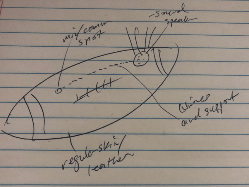
Drawings can be submitted to the USPTO as informal in two major ways. But, before we discuss submission to the USPTO – let’s first start with how drawings begin. Sketches, hand-drawn forms and figures by the inventor is as informal as it gets. However, this is how the invention is first explained to the Patent Attorney in a process called the invention disclosure.
Now, these rough drawings, sketches, pictures, photos, diagrams CAN be used to submit to the USPTO when filing a provisional patent application. I actually recommend sending as much as possible (multiple versions of sketches, drawings, rough sketches, partial sketches) so that we can have the largest body of information/disclosure available when it comes time to craft claims for the nonprovisional.
Here’s my best guess of what a preliminary sketch for our Football Patent example might have looked like (see below). Showing the primary features of a microphone, speaker, wiring/power (hidden) and its outer skin/leather.
When it comes time to submit a nonprovisional patent application, formal drawings are required and must meet the strict requirements (as discussed in Section 3 below).
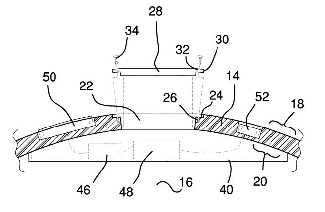
You can see a cut-through (also called section) view of our football example, which would be difficult to fully describe in words. Further, a formal drawing here makes sense because the details are so important showing the different material types, cavity and electrical wiring/systems involved.
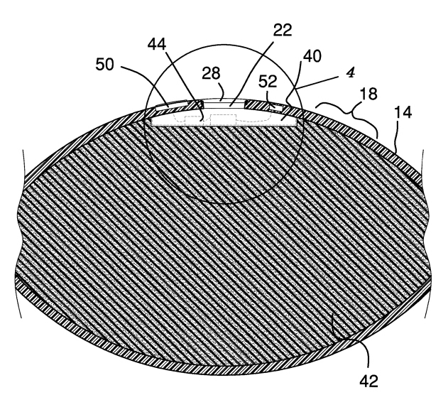
In fact, this drawing wasn’t specific enough for the fine details of the speaker/audio system. So, you can see the ITALICIZED “4” in the drawing above, which points to a circle where more detail is shown in a separate drawing (which is shown below).
At this point, the Patent Attorney knows what the claims will be, and can structure the written specification, and therefore decide which drawings to include or which to strategically not include to provide just enough disclosure and support for the claimed invention.
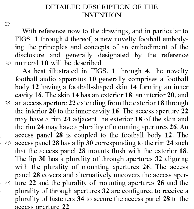
Guidelines for Creating Effective Patent Drawings
Creating effective patent drawings requires meticulous attention to detail and a thorough understanding of the invention. The first guideline is that the drawing should be clean, clear, and comprehensive, detailing every feature of the invention. This includes not only the prominent parts, but also minor details that contribute to the function or usage of the invention. The patent examiner will heavily rely on the drawings to understand your invention, so all pertinent information should be conveyed accurately and unmistakably.
Next, you should adhere to the rule of proportionality and consistency. This means all elements of the invention should be drawn to scale and should remain consistent across all the figures in the drawing set. For instance, if a part appears in multiple figures, it should look identical each time, and the reference numerals used to denote each part should also remain the same. This helps to avoid confusion and maintain a clear and consistent representation of the invention.
Lastly, it’s important to include various views of the invention in the drawings. This might include top, bottom, side, cross-sectional, and perspective views. The more angles you can provide, the more complete the understanding of your invention will be. You should carefully choose the most revealing and informative views, with an emphasis on those that best demonstrate the unique features and operation of your invention.
It’s important to remember that the primary goal of patent drawings is to complement and elucidate the written description of your invention, making it as clear and comprehensible as possible.
Section 2: What are Different Types of Patent Drawings
Perspective Views
This is also called an isometric view, and is usually the image on the front cover of the patent, as it is what the invention looks like in real life, although its a 2D drawing.
It allows both examiner (and potentially judge/jury) to gather what the invention is with one picture – and goes very well with the Abstract section of the written specification.
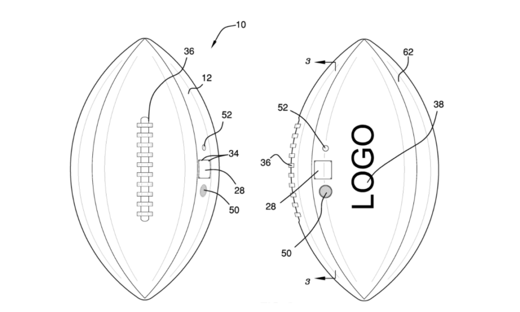
The view should be oriented to provide as much detail as possible to showcase the invention (meaning in our football example, we would want to make sure the audio speaker was visible).
Here are the perspective views of our football:
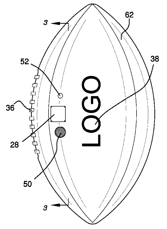
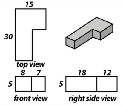
Front, Side, and Top Views
These views are taken from only one perspective at a time, and provide details of the invention that might not be seen from the one isometric view.
I like to think of these views as if you put your invention in a huge (6-sided) cube made of glass, and took an image looking through each of the 6 sides.

The top and bottom views are also called “plan” views, and the side views are also called “elevation” views. These terms are important, as different CAD software will use these terms, and locking in a view for use in a patent drawing will be vital.
Typically, there is one “front” view – which showcases the most features/elements of the invention, and this “front view” is associated with the surrounding elevation views (other sides) as well as the top and bottom, and helps to orient the various views.
The selection of this front view is very important because it will (by definition) determine the other views. You can see from the below picture, how this works:
Sectional Views
This is when it is important to showcase the inner parts of a 3D body. Our Novel Football Audio Apparatus example uses section views to showcase its audio and systems as well as the relationship between the ball structure and the electronics/hardware.
In order to properly show a section view, it is critical to define the cutting plane. In our example, the cutting plane is shown in the front view of the ball in figure 2. See below the cutting plane 3 (with associated arrows) and then the cut-view figure 3.
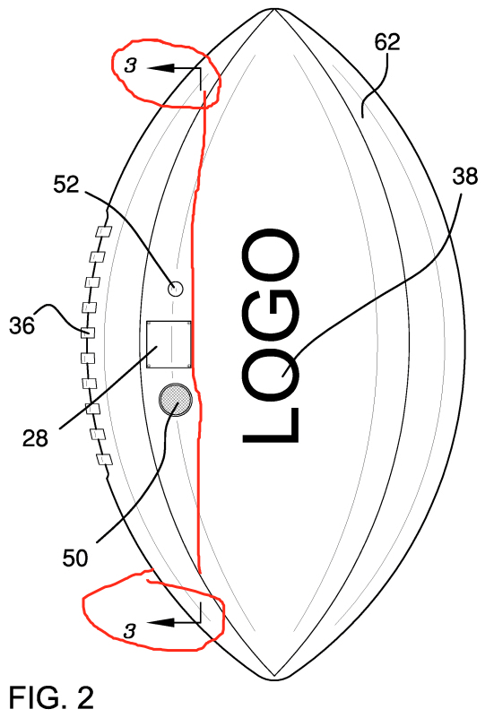

You can see the red highlighted Figure 2 on the left, showing the cutting plane. It’s literally like if you cut the football right along the red line, and looked left the figure on the right is exactly what you’d see.
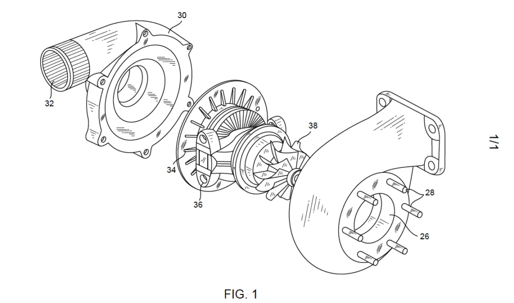
Exploded Views
These types of views show the structural relationship between components that are too small to be shown/differentiated in a standard fixed view.
These types of views are helpful for complicated mechanical drawings that have parts that would be nearly impossible to draw in a fixed drawing due to hidden nature, stacking, close proximity to other elements/features.
Here is an example of a motor/gear assembly that is best shown in an exploded format.
Graphs and Charts
This is a great opportunity for the inventor to show off the novelty or improvement of an invention as compared to prior art solutions.
Example charts could show the change in material strength, absorption, resistance, durability, quality, for example.

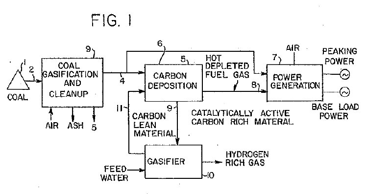
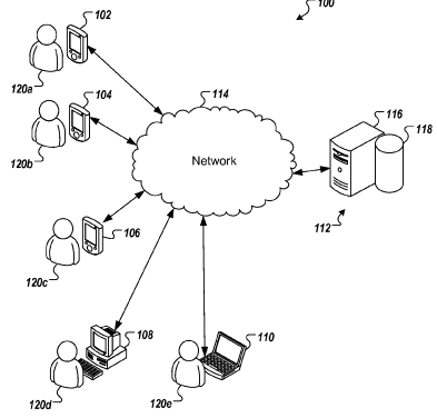
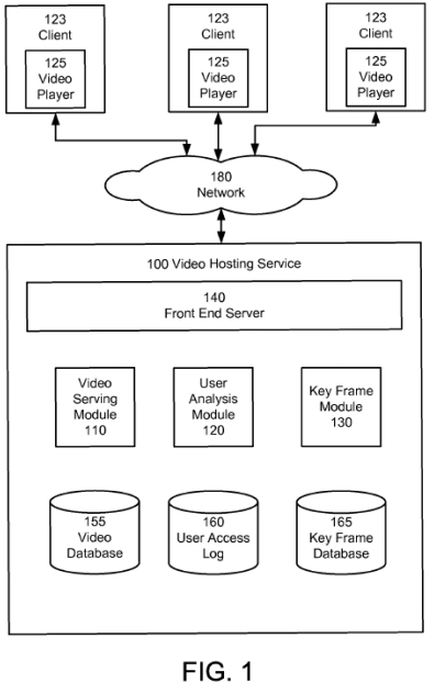
Flowcharts and Schematics
These are very useful for computer-implemented applications, where the claim is usually a method claim or process (with steps). And a flowchart shows very well the relationships between various steps in time/sequence.
There are standard symbols used in various flowcharting processes, the USPTO will not require specific project management standards – all they require is consistency across similar blocks so they can be easily understood by the examiner (and by people in the industry/skill).
Types of Lines
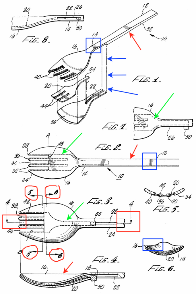
When you think of football, following our example above for the Novel Audio Football patent. What else do you think of? Food! BBQ/Grilling! Ok, cool – so, I found this patent from 1989 which is a novel “Combination Fork/Spoon Utensil” US Patent 4,835,864. See image below, which I’ll refer to with different types of lines.
Object lines are those that make up the majority of the solid lines around an object. These are solid lines that show the boundaries of the element. You can see these all over the below drawing, but are shown with a red arrow throughout.
Cutting plane lines, which we discussed above are shown here in red circles (you can see cutting planes 4, 5, and 6). Note that the direction of the plane’s cut matters. If you look to the right, you see Fig. 6, and if you look left, you see Fig. 5.
Projection lines show up when a figure is showing a relationship between two or more parts that are being exploded or distorted for visual purposes. In Fig. 1 below, you can see the projection lines, see blue arrows showing the line. This exploded view allows each of the nested elements (spoon and small fork) to be shown clearly.
Hidden lines are shown as dashed. You can see the hidden lines (shown in green arrows below) which are not present if the object were before you, but can show unique relationships and aid in understanding the functionality and positioning of the hidden elements/features.
Centerlines are shown when there is a need to demonstrate an axis or point of intersection/inflection. You can see the red boxes below showing the centerline of the cut-view/section-view 4. These have mixed dashed and long dashes.
Shading is highlighted below in blue boxes, and is all over these drawings. The shading helps the viewer understand that the pieces are not hollow, and have solid material/thickness. Shading also helps to show curvature. You can see the fork shading is curved, to help demonstrate the 3D geometry of the object.
Section 3: What Rules Must be Followed for Patent Drawings?
The technical rules are found in full in 37 CFR 1.84 and MPEP 608.02. Before a USPTO Patent Examiner gets to review/search/examine the patent application – first the drawings (and the whole specification for that matter) must pass muster through the formal requirements department first.
There are many formal requirements, as can be found in the above-referenced link. The main test is whether the drawing is “suitable for reproduction”. This means not only are the actual drawings something that can be easily copied but the drawings are clear enough so that the invention can be easily made/built by following the drawings.
If the drawings do not meet the formal requirements, the drawing will be deemed “informal”, and must be corrected if formal status is desired.
- What should be included?
- What should be excluded?
Paper Type, Size, and Margins
If you do send in paper drawings via mail, the paper must be flexible, strong, white, smooth, non-glossy, and durable. The paper should be high quality to withstand erasure. The size should generally be 8.5 x 11 inches (DIN size A4).
With the advent of electronic submission of patent documents, the actual paper size and type don’t matter so much. What matters a lot these days is the margins. The patent office will reject drawings for not adhering to margins which are as follows:
- 2.5 cm top margin
- 2.5 cm left margin
- 1.5 cm right margin
- 1.0 cm bottom margin
Scale
Patent drawings need only be drawn in proportion to each other – there is no requirement for scale size to any real-life prototype or model. As it is true, no real prototype is required to seek patent protection.
The drawings must be of a certain scale so that they are still readable if the paper/drawings are reduced by ⅔ without blurring lines or features. This is to reduce the size of data/images for the USPTO.
Arrangement of Views
Nothing tricky here – the views should follow a logical path, which is also sequential and numerical if possible. The flow is also generally more high-level/generic views progressing into more detailed views.
An important note is that the views must not overlap, and views should always be no larger than one page. It is permissible to have multiple sheets per view, but it will likely confuse the examiner and anyone else trying to understand the invention.
Each view on the same sheet must also have the same orientation (landscape, portrait, or angled).
Lines, letters, and Reference Numbers
For this part, I’m going to go back to our Novel Football Audio Apparatus patent, and focus on Figure 1 and show how the reference numbers are associated with the written description (specification).
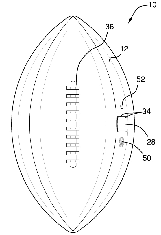
You can see on the right, is a snapshot of the detailed description of the invention. Each of the reference numerals on the left image showing the football (10, 12, 28, 34, 36, 50, 52) are discussed in the description on the right side.
10 is described as the “audio apparatus”; 12 is “football body”; 28 is the “access panel”; 34 is the “fasteners”; 36 is the “imitation laces”; 50 is the “speaker”; and 52 is the “power button”.
Referring to reference numbers is a very effective way to describe the invention fully and can help the examiner really grasp what is being discussed and how each part interrelates.
Common Mistakes to Avoid When Creating Patent Drawings
When creating patent drawings, there are certain common mistakes to avoid to ensure the accuracy and effectiveness of your drawings. First, one should steer clear of ambiguity or vagueness in the drawings. It is crucial to clearly illustrate the invention’s features and functions without leaving room for interpretation. This includes using precise lines, shading, and labeling to provide a comprehensive representation of the invention.
Another mistake to avoid is the omission of crucial details. Patent drawings should encompass all essential elements of the invention, highlighting its unique aspects. Neglecting to include specific dimensions, proportions, or important components can lead to an incomplete and potentially invalid representation of the invention. Accurate depictions and attention to detail play a significant role in obtaining a strong and enforceable patent.
Finally, it is crucial to adhere to the guidelines and standards set by the patent office. Failing to comply with these requirements can result in rejections or delays in the patent application process. Familiarize yourself with the patent office’s rules regarding drawing size, margins, numbering, and font styles and make sure to stick to these guidelines.
Seeking Guidance
Creating accurate and effective patent drawings is crucial for a successful patent application. However, navigating the intricacies of patent law and drafting high-quality drawings can be challenging. A knowledgeable patent attorney at Bold Patents can assist you in ensuring that the drawings you include in your patent application accurately represent the invention while complying with all necessary guidelines. We can help you improve your chances of obtaining a strong and enforceable patent. Contact us today to begin the process of filing for your patent.
Summary
I hope this guide was a helpful explanation of Patent Drawings generally, and that you now feel more comfortable with how to read and understand a patent application or a granted patent that has been published.
If you have questions regarding the patent process or patent cost, you can follow the links below:
- Blog Article: How to Patent an Idea
- Blog Article: How Much Does a Patent Cost
If you have any questions about patent drawings, or patents in general, book a free consultation with us today!